

TW200 Battery Cradle
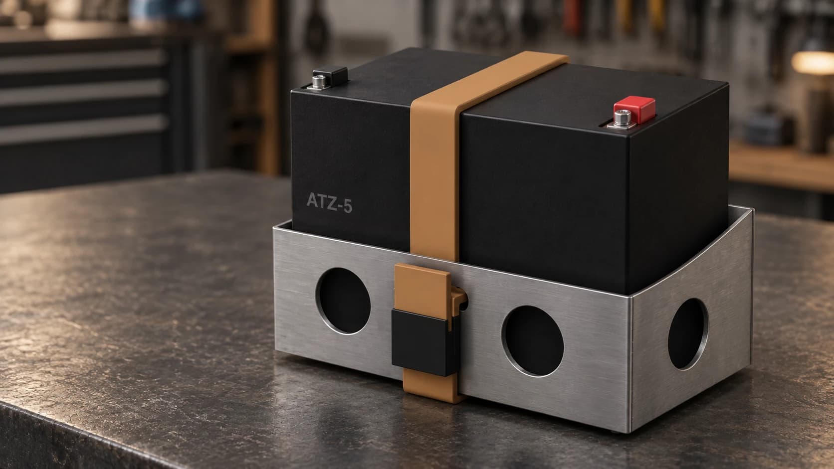
A low steel cradle for a TW200 scrambler, with round ports, a purchased retaining strap, and curved sides rising toward the rear.
Origin.
The battery needed a home that suited the bike and could be made with the tools already in the shop. We wanted a small, deliberate piece of the scrambler’s design, with the battery visible above the steel and the strap part of its appearance.
The work began with two reference photographs and the nominal dimensions on the battery packaging. We described the intended look, the plasma cutter, and the assembly method in plain language. Codex, connected to Autodesk Fusion through MCP, carried those requests into an editable model and a provisional cut plan.
How it works.
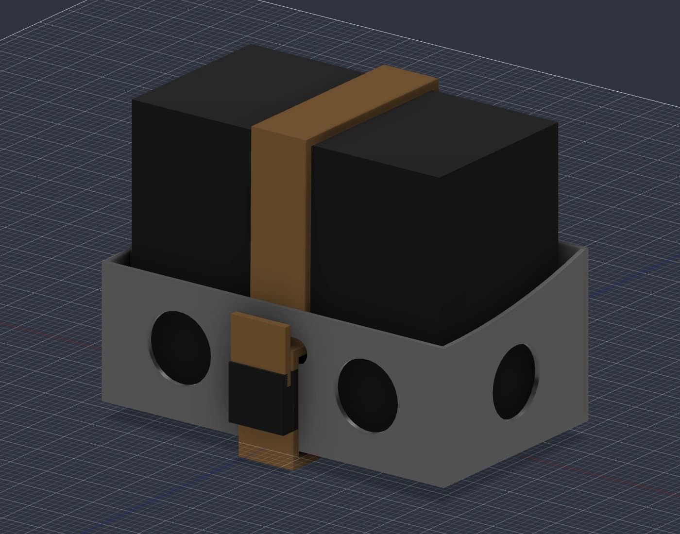
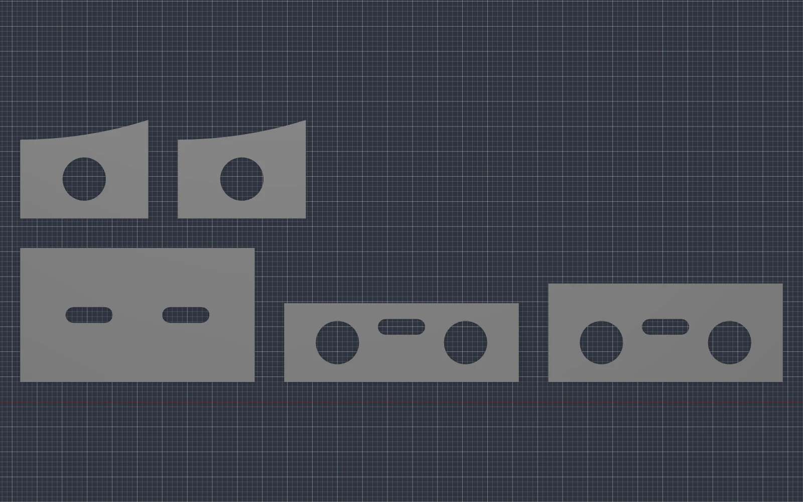
Five flat panels form the cradle: a base, front, rear, and two sides. The design assumes approximately 1.52 mm mild steel, cut on a Langmuir CrossFire and welded or brazed together. The curved upper edges are profiles in flat sheet, so they require no bending.
The front wall is 40 mm high and the rear is 50 mm. Six large round ports keep the detail simple. Pads support the battery, while a purchased Voilé strap passes through slots in the front and rear, over the battery, and underneath the base. The mounting blanks remain loose until their positions can be checked on the motorcycle.
Current state
Status / Pre-prototype
Pre-prototype.
Pre-prototype. The Fusion model, STEP assembly, cutting drawings, and CAM review files are prepared. Digital checks covered dimensions, orientation, interference, cut profiles, and selected posted toolpaths. Exporting and reopening the Fusion file preserved the model and CAM. The cradle has not been fabricated or fitted to the bike. The cutting recipe, mounting location, and retention performance still need physical testing.
Build notes
From the work.
Lower proportions and a higher rear
The earlier box covered too much of the battery. Lowering the walls gave the strap more presence and left a lighter silhouette. A later request was simple: “Let’s add a curve to the sides so the back is a little higher than the front.”
That became a shallow rise along each side, meeting a taller rear panel. The front and rear panels stayed straight across their widths. The change gave the cradle a more considered profile while preserving the five-panel construction.
From conversation to Fusion
MCP is the connection that lets an AI application use external tools. Here, it allowed the agent to write and execute Fusion API scripts, inspect the results, and revise the design. Our inputs were reference images, shop constraints, and ordinary design feedback.
The conversation continued through CAD and CAM. Asking for lower walls changed the model; specifying a bought strap changed its routing and clearances; asking for the higher rear changed both the assembly and flat cutting profiles. Fusion then regenerated the toolpaths.
The useful result is an editable design and the files needed to keep developing it. This was an iterative design review: we supplied the purpose, appearance, and machine details, then checked what came back. The same approach carries from software into a part we intend to make in the shop.
CAM for the plasma table we have
Our CrossFire uses a Razorweld Razorcut 45 with fixed manual torch height. It has no powered Z axis, initial height sensing, or torch height control. Large openings and broad curves suit that constraint; fine decorative cuts add little to this part.
Fusion has separate setups for a calibration coupon, the five panels, and the optional mounting blanks. The CAM includes a named plasma tool, kerf compensation, lead-ins, holding tabs, and openings cut before the outer profiles. Langmuir’s official FireControl post is configured for review with IHS and THC disabled.
The controller choice still needs confirmation before releasing a program. Feed, kerf, pierce dwell, and manual stand-off remain provisional until a coupon establishes the recipe for the actual sheet and consumables.
The first build has specific questions to answer
After the remaining toolpath review, simulation, dry run, and coupon cut, the first assembly will check the panel fit and distortion through joining. On the bike, we will check pad fit, strap clearance, terminal access, mounting positions, and retention under vibration. Those results will shape the next revision.